The challenge
A plastic High Density Polyethylene container is supposed to protect its contents, in some cases even when it falls. To test this, drop tests are performed. The contents of a container can influence its behaviour during a drop test.
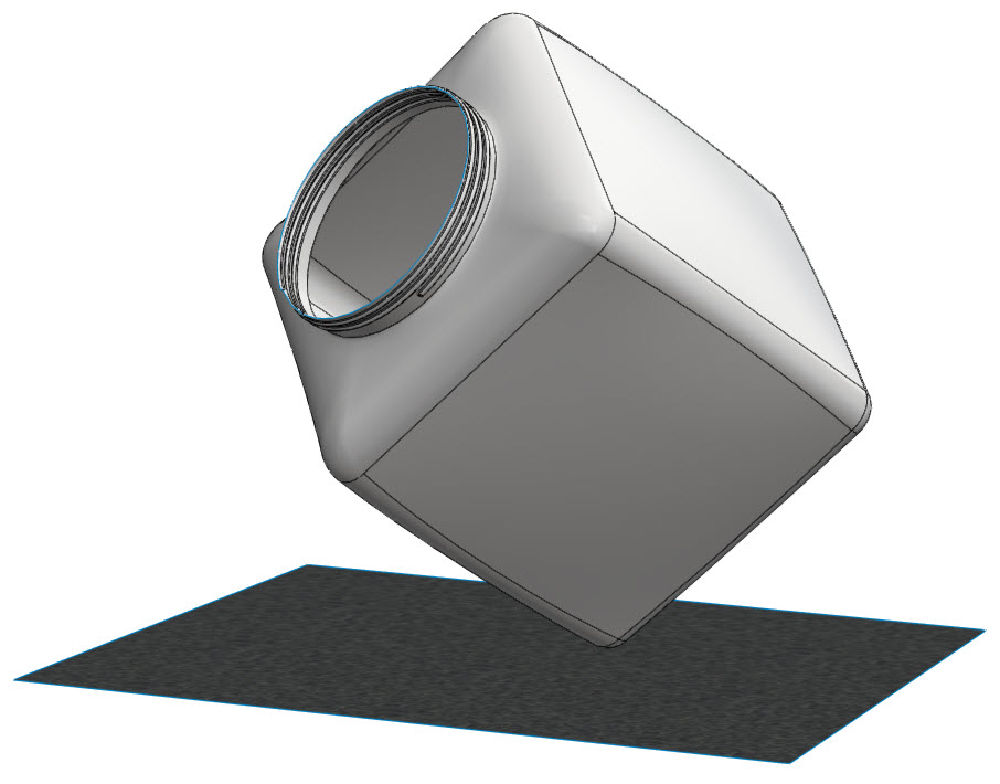
With Abaqus Explicit, it is possible and quite straight forward to simulate a container with water in it using a CEL approach. But what if the container contains sand, stones or pallets, which consists of small particles? How can we model this? Sand can flow, similar to fluids. But it can also pile up, something fluids will not do. There are different approaches to modelling it thinkable, depending on the intended application. In this case, we will investigate the use of Abaqus’ discrete element method (DEM) for this purpose even though the CEL approach could also be used for that. DEM is a relatively new technique in which particles are individually modelled.
Getting the particles there
In order to perform the simulation, the particles first need to be placed in their initial position. DEM is not supported by the Abaqus CAE interface yet, so its use requires some modifications to the input file. Either the nodal position can be specified directly, or a particle generator can be used. In this case the particle generator will be used, which is new in Abaqus 2016, and the final position of the particle will be determined by gravity.
The particle generator
The particle generator generates particles from an inlet surface. The particles can have random sizes based on a user-specified probability density function. They are generated with a specified mass flow rate and initial velocity, both can vary in time. A maximal number of particles must be specified, after which the particle generator stops. In a *DISCRETE SECTION the properties of the particles are defined, including the density and a (probability density function describing the) radius. In this case, particles with a radius of 8 mm are used. This is too large for sand, but it limits the amount of particles needed to fill part of the container and thus reduces computational time. A maximum of 750 particles is generated. Parallel execution is not possible using the particle generator and this type of simulation requires some patience: in my example, simulating the initial position of the particles took about 10 hours. The result looks like this:
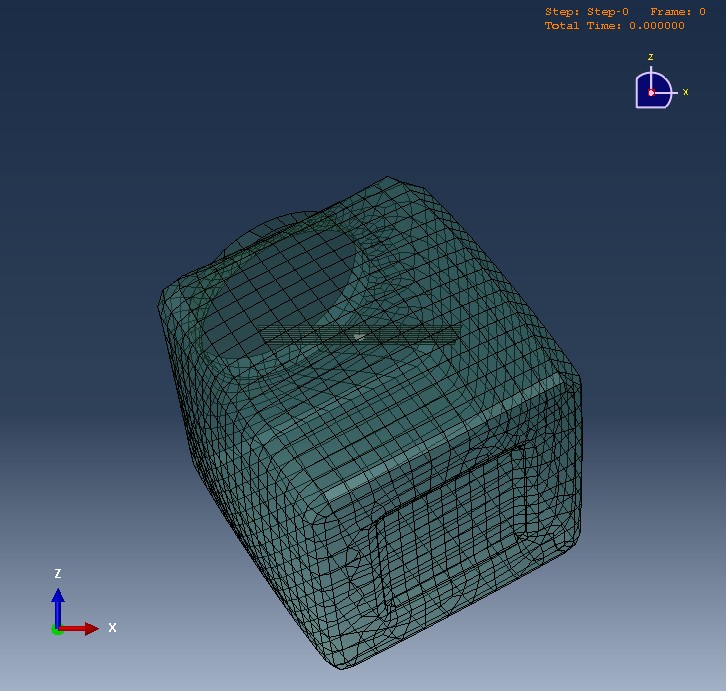
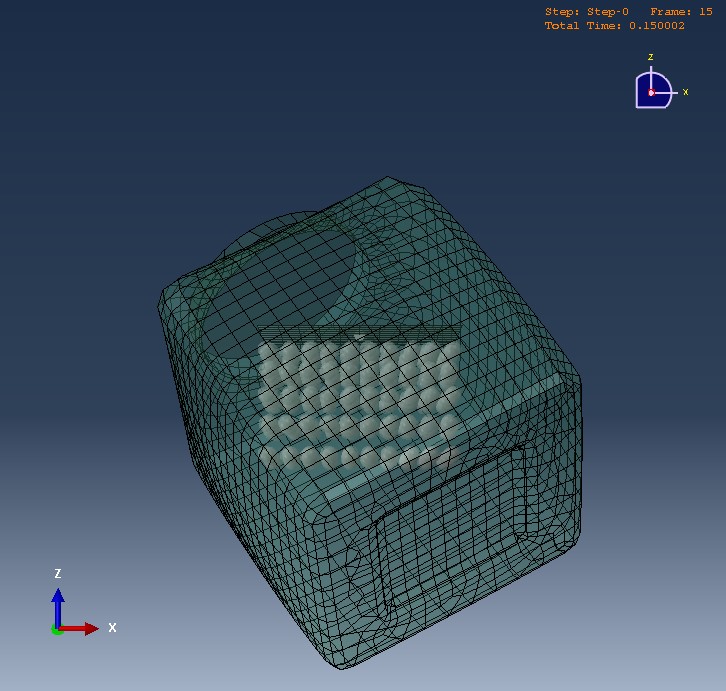
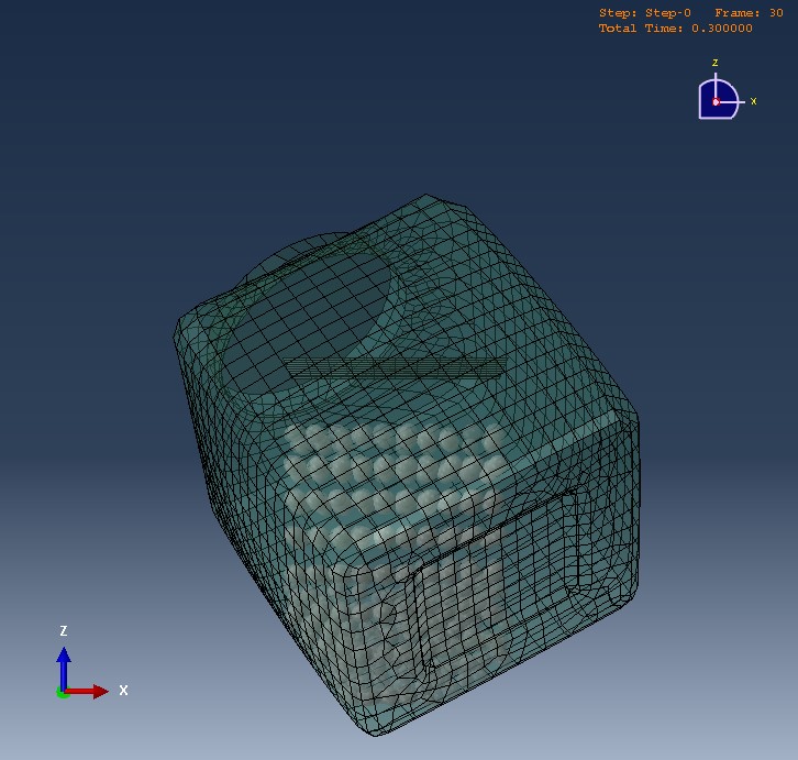
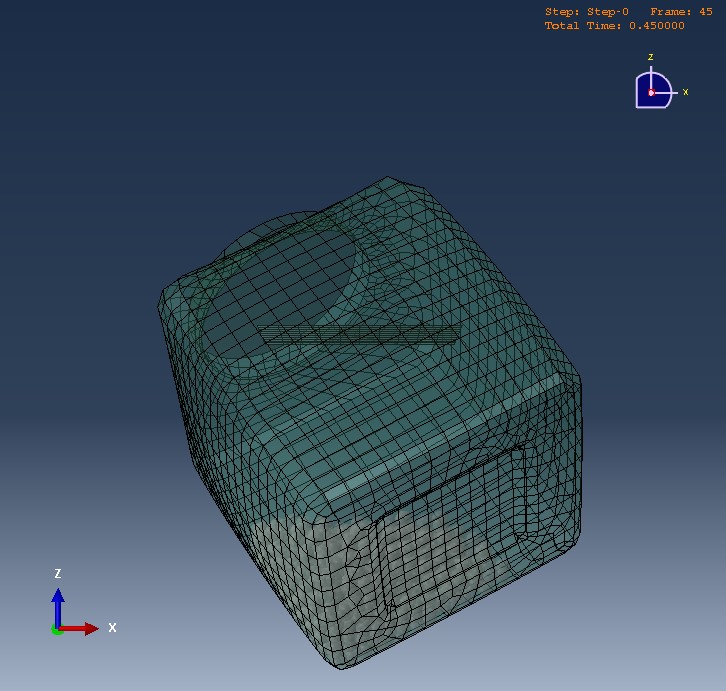
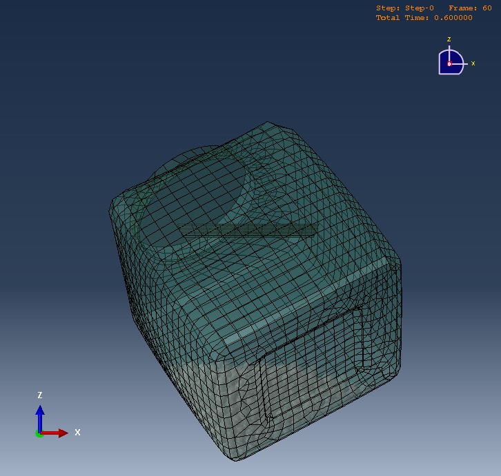
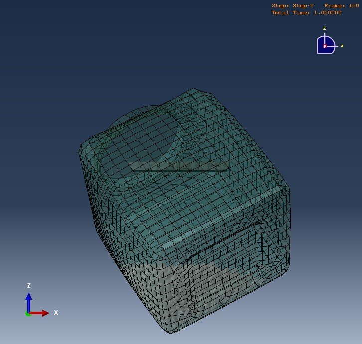
Including more particles, to have a more filled container, significantly increased simulation time: simulating twice as many particles took more than three times as much time. For testing purposes, the version with 750 particles is used.
The drop test
To simulate the drop test, a second simulation is performed, where the initial location of the particle corresponds to their location at the end of the first simulation. A rigid surface is located underneath the container and an initial velocity corresponding to a drop height of about 30 cm is prescribed to the container and particles. Contact between the particles, between particles and container and between container and surface is defined.
An elastic-plastic material definition is used for the polyethylene of the container, with the isotropic hardening curve defined by several data points; the onset of plastic yielding occurs at 8.618 N/mm2, and failure occurs at a strain of 0.59. Damage is incorporated using a ductile damage definition. The high-density polyethylene has a density of 8.76 × 10⁻⁷ kg/mm3, Young's modulus of 903.114 N/mm2, and Poisson's ratio of 0.39. Source of material information: Abaqus example problems guide 2.3.2 Impact of a water-filled bottle.
Approximately 40 hours later, the results were there. See video below:
Conclusion
The animated results in the video impressively captures the individual movement of the different particles and can be observed as they contact each other and the container. The particle generator greatly simplifies setting-up the model. It seems possible to use DEM to model (sand) particles during a drop test.
While it was interesting to work with DEM and perform a simulation like this, there are some drawbacks. Because it is not supported via the CAE, setting up the model takes quite some time. Furthermore, the simulations are computationally expensive. That it is currently not possible to use parallel processing for the particle generation does not help in this matter. Also, currently particles with a radius of 8 mm where simulated, while sand is much smaller. If the actual size of sand grains is taken into account, the simulation would take an unrealistically long time.
So, in conclusion, while DEM is an interesting feature included in Abaqus Explicit, it may not be the most suitable method to simulate a drop test with sand. In this case, using CEL with a Drucker-Prager material model may be more suitable. While CEL simulations tend to take long as well, the increased simulation time with an increased number of sand particle would not be as big. For simulations with larger particles, where a continuum approach is not reasonable, DEM could be very valuable and the way to go.
Are you interested in this technology, or doubting to outsource a Droptest simulation to us?

 Advanced Simulation


 Engineering

 PLM
PLM
