Connection between the vehicle battery and the charging station
Nowadays, there are great demands for high-performance charging stations for electric vehicles (EVs). The growing market for EVs and the increasing demand for faster charging times are driving this development. High power DC fast charging stations are widely used in the electric vehicle industry to enable fast charging of EV batteries. Vehicle charging connectors are critical components that enable a smooth connection between the EV's battery and the DC charging line. In this article, we will focus on these connectors and the associated charging cable. CST Studio Suite enables efficient design through coupled electromagnetic (EM) and thermal simulations.
What is CST Studio Suite?
Dasssault Systèmes' CST Studio Suite combines various simulation techniques, including finite element (FEM), finite integral techniques (FIT) and others, to efficiently couple electromagnetic, thermal and mechanical effects. This makes them particularly useful for the development of complex systems where multiple physical phenomena interact with each other. Learn more.
...
The necessity of simulation
DC charging stations deliver high power levels and generate considerable heat in the process. This heat can affect the efficiency and safety of the charging system. These high temperatures necessitate the use of liquid cooling systems. A coupled electromagnetic-thermal simulation plays a crucial role in speeding up and simplifying the development phase. Key aspects such as thermal management, efficiency optimization and design validation can be improved through these simulations.
Charging methods for electric vehicles
The charging station offers three power levels for electric vehicles:
Level 1: Charging with a charging adapter on a standard household socket with up to 7.4 kW power is the slowest method. This method is well suited for charging at home at night.
Level 2: A socket with a higher AC voltage is suitable for private and public charging stations. A 3-phase current with 400 V voltage enables higher outputs. It offers an output of 7.4 kW to 22 kW.
Level 3: DC fast charging supplies the vehicle battery directly with direct current, bypassing the onboard charger. The speed of fast charging depends on both the charging station used and the maximum charging power that the vehicle can handle. This method is ideal for long-distance journeys where fast intermediate charging is required.
Let's look at the different stages using an example. The Merzedes-Benz EQS 450+ model has a 107 kWh battery, which enables a range of 635 km [1].
Table 1 [1] shows the different ways to charge the Mercedes-Benz EQS 450+ with alternating current (AC). It is important to note that some charging methods may not be widely available in certain countries.
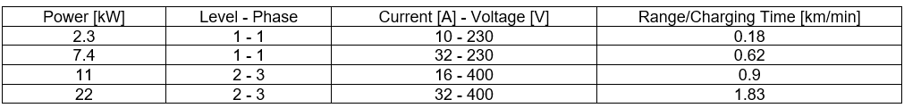
Table 1: Options for charging the Mercedes-Benz EQS 450+ with alternating current
Level 3 fast charging enables longer journeys by adding maximum range in the shortest possible time. However, as soon as 80% of the battery capacity is reached, the charging power is significantly reduced.
Table 2 [1] summarizes the information on fast charging of the Mercedes-Benz EQS 450+, including the maximum DC power of 207 kW.
Table 2: Options for charging the Mercedes-Benz EQS 450+ with direct current
Standards for DC fast charging
With the increasing demand for fast charging of EVs, the need for a well thought-out design for DC charging stations is also growing. Various standards have been developed worldwide for this purpose. Figure 1 shows the three established DC fast charging standards, which vary depending on the car manufacturer and country of origin.
- CHAdeMO: mainly used by Japanese and Korean EV manufacturers such as Nissan and Kia.
- CCS (Combined Charging System):
- Global standard developed by leading car manufacturers in North America and Europe.
- AC and DC charging capabilities in one plug.
- Charging with Level 1, Level 2 and DC fast chargers with the same plug.
- Type 1 in the USA, type 2 in Europe.
- Tesla Supercharger:
- Proprietary DC fast charging network operated by Tesla.
- Can only be used by Tesla vehicles.
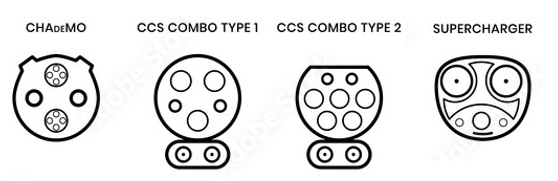
Figure 1: Types of plugs for electric vehicles
Exemplary data sheet information of a DC charging station (CCS)
The development and integration of high-performance charging stations are key steps in promoting electromobility.
Table 3. shows the most important parameters and the corresponding sample data from the Phoenix Contact data sheet, which are crucial for an efficient EV charging station:
Table 3: Most important parameters and corresponding values for an efficient EV charging station
Components of the charging station
The development of an efficient and powerful DC charging station requires a precise and methodical approach. This section of our blog presents the charging station components that we have modeled. Figure 2. shows the entire charging connector with the connected charging cable as well as an enlarged view of the connector and the battery. The connector consists of pins (red parts), which are connected to the charging cable, and the vehicle socket (purple parts), which is integrated into the electric vehicle and connected to the battery. These mechanical parts provide the electrical contact. The other parts in Figure 2 are:
- Cable: The wires through which the current flows.
- Charging current: 500 A
- Diameter of the PTFE sheathing: 36 mm
- Conductor structure: 4 × 25 mm²
- Cooling
- Cooling hose diameter: 1 × 11.5 mm + 2 × 8.8 mm
- Inlet temperature: 15°C
- Flow rate: 2 l/min water
Fig. 2: Complete charging connector with charging cable and enlarged view of the connector
Setting up a multiphysics simulation (EM thermal coupling)
The simulation settings in CST Studio Suite include:
- Material definition: The model consists of metallic connectors, the water cooling, the piping, the copper cables, the plastic handle of the charging plug and the outer sheath of the cable. These materials were taken from the CST library.
- Boundary conditions for electromagnetic and thermal simulations
- Definition of the background for EM and thermal simulations
- Selection of the "Stationary Current" solver for electromagnetic simulation and "CHT" solver for thermal simulation
- Define sources for the EM simulation with "Current Port"
- Definition of the cooling parameters, e.g. water inlet with defined temperature and flow rate, for the thermal simulation
Electromagnetic simulation
The electromagnetic simulation includes various analyses and visualizations. The calculation of the total losses and the voltage distribution are shown in Figure 3. Referring to the table in Figure 3, the total losses at the charging station are 448 watts.
Figure 3: Total losses and voltage distribution
Thermal simulation
Thermal simulation is a challenge, especially in terms of the mesh structure for large models. The model is large and extends in the x, y and z directions, which means that the mesh must be as fine as possible in all three directions. The mesh size must be sufficiently small to achieve convergent results from the simulation. However, if the number of mesh points is not sufficiently large, the convergence criteria will not be met even after many iterations, which can affect the accuracy of the simulation results. Therefore, the mesh comprises more than 16 million elements.
Figure 4 shows the CFD mesh structure of the model. Such a fine mesh structure requires considerably more time for a precise simulation. Therefore, the consideration of convergence criteria such as "equation balances" is of great importance. "Equation balances express how well certain physical quantities such as mass or energy are maintained throughout the entire calculation area.
Figure 4: CFD mesh structure of the model for CHT simulation
The heat transfer equation, turbulence equation, momentum equation and pressure equation are solved by CST with the CHT solver to calculate all important parameters such as temperature distribution and coolant velocity. Figure 5 shows how the equation balances are reduced with several iterations and how the equations converge.
Figure 5 Equation Balances
Results and validation
In this section we look at the thermal distribution at a current of 350 A. Figure 5. shows the temperature distribution under this load.
Figure 5: Temperature distribution under a load of 350 A current.
The temperature ranges from 15 °C to 30 °C. The hottest area of the cable is in the middle of the cable sheath with a temperature of 26 °C. The handle of the cable also has a temperature of 25 °C. The hottest part of the connector reaches 29 °C.
Initially, we modeled and simulated charging stations with a current of 350 A, which are often used for fast charging electric vehicles. In a further step, we increased the current to 500 A in order to analyze the effects of this increase on fast charging in modern charging stations. A particular focus here is on investigating the correlation between the increased current and the resulting increase in temperature.
We now look at the thermal distribution at a current of 500 A. Figure 6. shows the temperature distribution under this load. The temperature ranges from 15 °C to 42 °C. The hottest area of the cable is in the middle of the cable sheath with a temperature of 30 °C. The handle of the cable has a temperature of 25 °C. The hottest part of the connector reaches 42 °C.
Figure 6: Temperature distribution under a load of 500 A amperage
These simulations show how the temperature distribution changes at different amperages and help to identify and solve the thermal challenges in the development of charging stations.
In our experience
Using the CST Studio Suite to carry out coupled electromagnetic-thermal simulations offers decisive advantages in the development of charging systems for electric vehicles:
CST Studio Suite provides the CHT solvers to study the charging system. The advantages of coupled electromagnetic-thermal simulation are listed and explained below.
- Increased thermal efficiency: Targeted simulations can optimize heat dissipation and improve overall performance.
- Optimization of material properties: Simulation helps to fine-tune material properties such as thermal conductivity and specificheat of component to achieve the best results.
- Hose geometry: Analysis and optimization of the cooling geometry contributes to better heat dissipation and efficiency.
- Shorter development phase: Early simulations allow problems to be identified and solved more quickly.
- Reduction of prototype testing: Simulations reduce the need for extensive physical prototyping and testing, saving costs and time.

 Advanced Simulation


