
 Advanced Simulation

Thermo-Electromagnetic and Thermomechanical in CST Studio Suite and SIMULIA Abaqus Simulation Environments
Modern engineering challenges and continuous progress in the field of electrical equipment design and material systems force the contemporary engineer to move away from an isolated, single-domain approach to the analysis of physical phenomena. In the era of miniaturization, power density maximization, and the introduction of advanced composites, multiphysics modelling, referred to as coupled phenomena, becomes a key paradigm. This implies the necessity of simultaneously considering the interactions between electromagnetic fields, heat transfer, fluid dynamics, and solid mechanics.
Engineering tools provided by Dassault Systèmes, particularly flagship simulation software such as CST Studio Suite and SIMULIA Abaqus, offered and implemented by experts from TECHNIA, represent the absolute vanguard in virtual prototyping. They enable the creation of digital twins that reflect the real behaviour of complex systems under extreme load conditions with unprecedented precision. Understanding the fundamental laws governing these phenomena, expressed via Maxwell's, Fourier-Biot's, or generalized Hooke's equations, is essential for the correct configuration and interpretation of numerical results. Low-frequency electromagnetic phenomena are grounded in Faraday's law of induction, Ampère's law, and Gauss's laws, which together describe how time-varying magnetic fields induce electric fields, and how flowing currents generate magnetic fluxes. In lossy media, this process involves the irreversible conversion of electromagnetic energy into Joule heat, forming a bridge to the domain of thermodynamics. The generated heat disperses in accordance with the laws of thermal conduction, and the resulting temperature gradients lead to volumetric thermal expansion of materials, inducing local and global stress fields within them. These phenomena are fully interdependent, meaning that temperature-induced changes in material properties exert a feedback effect on the electromagnetic field distribution, creating a nonlinear, strongly coupled dynamic system.
To illustrate the power of modern numerical methods, it is worth conducting a deep analysis of two extremely different yet complex test cases. The first is a fully coupled thermo-electromagnetic analysis of an air-core power choke with a rated current amplitude of 1 kA, carried out in the integrated CST Studio Suite environment. Air-core chokes, lacking a ferromagnetic core, are critical components in high-voltage power engineering systems, higher harmonic filtration circuits, and DC converter stations. The absence of a saturating core guarantees excellent linearity of the inductance characteristic as a function of current, which is a desirable feature when suppressing short-circuit currents.
However, the lack of a core presents significant design challenges, as the magnetic flux is not concentrated in a closed magnetic circuit, but rather undergoes substantial dispersion in the space surrounding the coil. This leads to an intensification of electromagnetic field emissions outside the system, while inside the winding itself, it induces extremely complex current density distributions. To model this problem, a low-frequency frequency-domain solver (LF Frequency Domain) was utilized, operating on a discretization of the working space using the finite element method. This algorithm enables the precise capture of the skin effect and the proximity effect, which are crucial factors determining Joule power losses in conductors carrying high AC currents.
The skin effect causes current to be displaced toward the outer layers of the conductor due to the formation of eddy currents that oppose the main current, effectively reducing the active cross-sectional area of the conductor and drastically increasing its AC resistance. In turn, the proximity effect stems from the interaction of external, time-varying magnetic fields originating from adjacent coil turns on a given conductor, leading to a drastic asymmetry in the current density distribution across its cross-section. In the simulated air-core choke carrying high current, these two effects overlap in a highly nonlinear manner. The numerical solution allowed for the determination of the vector magnetic flux density distribution (Fig. 1), whose highest values were expectedly localized in the central part of the coil's geometric axis, creating a characteristic dipole field profile spreading outward from the coil.
However, a more critical result from a design perspective was the spatial distribution of current density (Fig. 2), which exhibits current density concentrations at the edges of the conductors located closest to the system's axis of symmetry. This geometric current distribution served as the direct basis for calculating power losses, including Joule losses, defined as the scalar product of the current density vector and the electric field intensity. The volumetric power losses calculated in this way constituted the input dataset (Fig. 3), a distinct thermal source map that had to be imported into the thermal solver space.
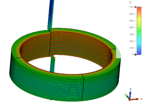
Fig. 1. Distribution of the magnetic flux density vector in the choke (CST)
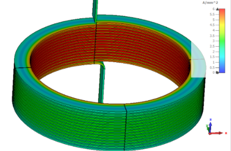
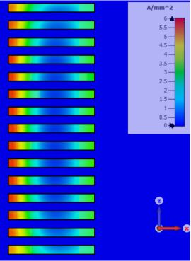
Fig. 2. Distribution of the current density vector in the choke rods (CST)
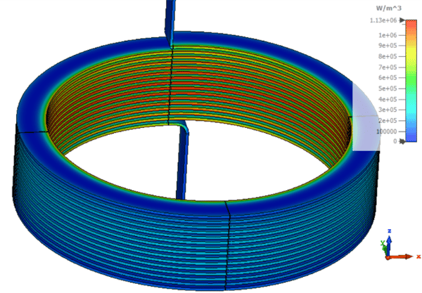
Fig. 3. Distribution of Joule power losses in the choke coil (CST)
Data transfer between the electromagnetic and thermal solvers in the CST Multiphysics Studio environment occurs in a lossless and automated manner, eliminating the risk of manual interpolation errors. To determine the steady-state temperature of the choke, simplified methods based on empirical heat transfer coefficients were not used; instead, an advanced conjugated heat transfer (CHT) solver was employed. This algorithm simultaneously solves the heat diffusion equations inside the copper conductors and the full Navier-Stokes equations describing the fluid dynamics of the air flow around and within the choke. Due to the absence of a forced cooling system, the phenomenon of natural convection—driven purely by buoyancy forces was analyzed. Air density variations resulting from local heating at the coil surface were accounted for using the Boussinesq approximation, which couples the temperature field with the momentum conservation equations of the air.
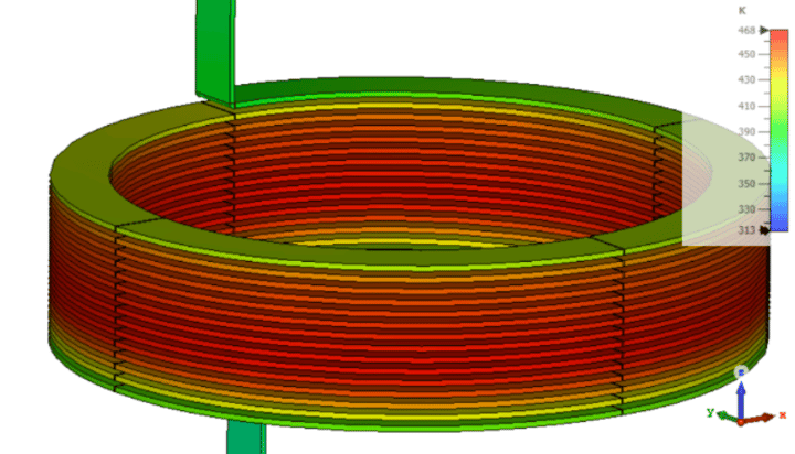
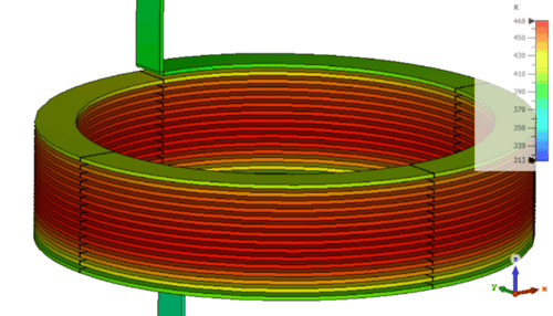
The numerical solution of this problem revealed a remarkably interesting picture of the thermodynamic system's behavior. The steady-state temperature distribution clearly showed that the areas with the highest temperatures were not located—as might be intuitively assumed—on the outer turns or at the very bottom of the coil, but were instead concentrated within its inner, middle layers (Fig. 4). Cooler ambient air was drawn from below into the channel formed by the turns, heating up intensely as it flowed upward. Consequently, the upper sections of the choke were washed by air at a significantly elevated temperature, which drastically reduced the heat dissipation capacity to the environment, leading to thermal throttling. These results, including precise temperature gradient maps, are invaluable for engineers designing electrical insulation, enabling the exact identification of critical hotspots and the optimization of spacing between individual winding disks to improve gravitational cooling efficiency.
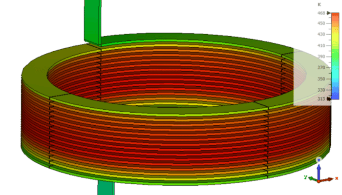
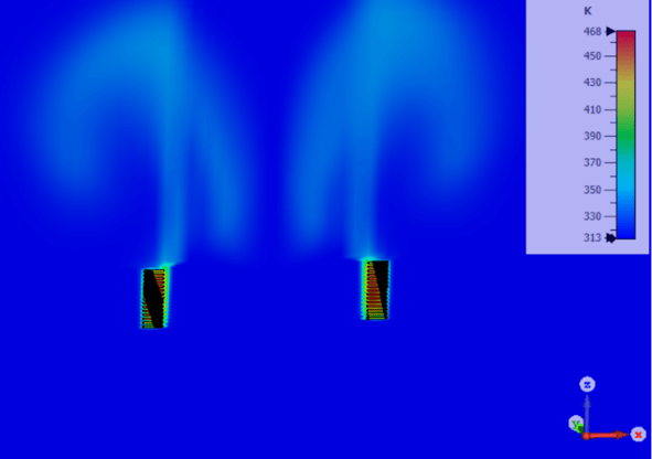
Fig. 4. Temperature distribution in the considered choke (CST)
While the first case dealt with a steady-state problem and a geometry devoid of ferromagnetic elements, the second problem under consideration represents a significant achievement in the field of virtual modelling of coupled phenomena, introducing the nonlinear fracture mechanics of brittle materials subjected to thermal shocks. This problem involved a thermo-electromagnetic-mechanical analysis in which thin ferromagnetic rods made of magnetite were embedded in a massive ceramic matrix and subsequently subjected to a cyclic heating process using an external, high-frequency electromagnetic field. Such composite structures find applications in catalytic reactors, advanced volumetric heating systems, and the aerospace industry, where materials with specific absorption properties and high chemical resistance are sought. Magnetite, being a ferromagnet with high magnetic permeability and relatively good electrical conductivity compared to other iron oxides, becomes an excellent energy absorber in a time-varying magnetic field. Conversely, the ceramic matrix, characterized by dielectric properties, is transparent to electromagnetic waves, meaning that the heat generation process occurs exclusively inside the ferromagnetic inclusions. This process is a prime example of the intentional exploitation of phenomena that are considered parasitic in transformers or chokes—namely, eddy current losses and hysteresis losses associated with the reorientation of magnetic domains within the material.
The electromagnetic simulation for this problem was again carried out using a frequency-domain solver, modeling the inductor surrounding the composite and accounting for the equivalent magnetization characteristics of magnetite. Calculations showed that the time-varying magnetic field undergoes strong concentration inside the rods, bypassing the insulating ceramic (Fig. 5). The high excitation frequency of the field, combined with the material properties of magnetite, resulted in a radical skin effect, causing eddy currents to be induced almost exclusively in a very thin, near-surface layer of the rods (Fig. 6). The current density and associated volumetric losses reached extreme values there, while the cores of the rods remained regions of negligible direct heat generation (Fig. 7). The result of this part of the analysis was a spatial map of heat sources with gigantic, local power density values. However, unlike the air-core choke analysis, evaluating the system's response in the time domain, temperature evolution, and eventual mechanical failure required transferring the data to a specialized environment dedicated to advanced solid mechanics—namely, the flagship system SIMULIA Abaqus.
The process of co-simulation and field mapping between computational meshes of different environments is a complex numerical challenge that requires strict adherence to the principle of conservation of energy. Vector and scalar physical quantities determined on the precise, dense electromagnetic mesh in the region of the rods had to be interpolated onto the hexahedral mesh of the Abaqus environment, while simultaneously accounting for the fact that both programs may utilize different shape function interpolation methodologies. Following the successful application of the thermal loads, a transient analysis was initiated in Abaqus, consisting of the coupled solving of heat conduction and elasticity equations in the time domain. The heating dynamics of such a composite are characterized by vast disparities. Magnetite underwent rapid volumetric heating, whereas the ceramic matrix absorbed this heat solely through slow conduction. Due to the negligibly low thermal conductivity of the ceramic, an extremely steep temperature gradient formed at the phase boundary between the two materials. From a thermodynamic perspective, heat could not diffuse deeply into the matrix fast enough, creating localized zones of overheating. The temperature distributions during the heating process are shown in Figure 8.
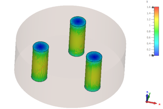
Fig. 5. Distribution of the magnetic flux density vector in the considered system with magnetic rods (CST)
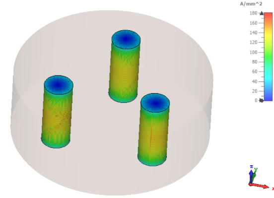
Fig. 6. Distribution of the current density vector in the rods (CST)
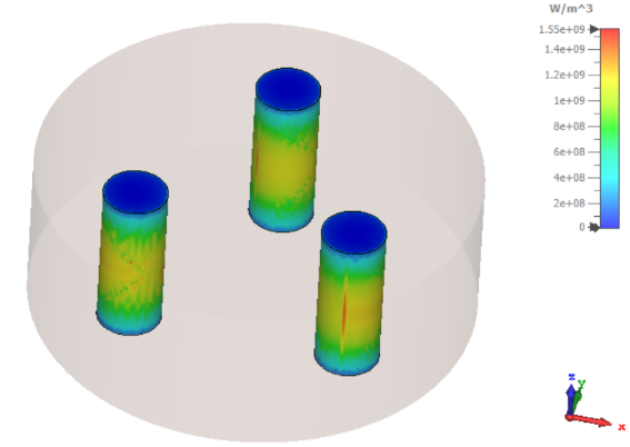
Fig. 7. Distribution of Joule power losses in the rods (CST)
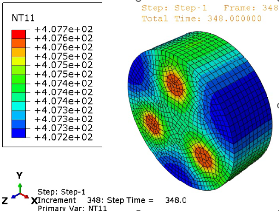
Fig. 8. Steady-state temperature distribution during the rod heating process (Abaqus)
These rapid temperature changes acted as a direct load for the mechanical equations. The critical driving factor proved to be the drastic difference in the coefficients of thermal expansion between the two materials. The expanding magnetite, characterized by a higher coefficient of thermal dilation, began to swell rapidly, meeting resistance from the rigid, thermally cooler in volume, and mechanically hard ceramic matrix. This kinematic configuration leads to a classic, albeit very intense, thermally loaded contact problem. The swelling rods exerted immense radial pressure on the surrounding ceramic, generating—in accordance with the laws of continuum mechanics—massive circumferential tensile stresses within it. While structural ceramics exhibit excellent resistance to isostatic compression, their tensile strength under uniaxial or biaxial loading is negligible due to the absence of stress-relaxation mechanisms through plastic deformation. Microscopic defects in the matrix structure instantly become stress concentrators. Initiating cracks once the critical stress intensity factor, defined in linear elastic fracture mechanics, is exceeded (Fig. 9).
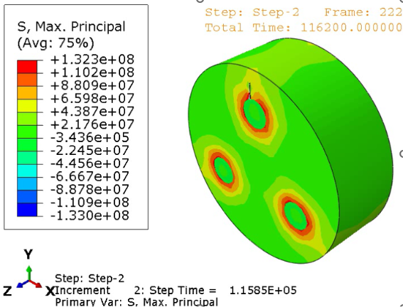
Fig. 9. Distribution of mechanical stresses in the ceramic – ceramic cracking (Abaqus)
The objective of the simulation was not merely to establish that the allowable stresses had been exceeded, an approach that is outdated and uninformative, but to conduct a full analysis of the material degradation process resulting from repeated heating and cooling cycles. Such a phenomenon, known as thermal fatigue of brittle materials, requires the implementation of advanced damage propagation algorithms. In Abaqus, the Extended Finite Element Method (XFEM) was utilized for this purpose, which allows for the modelling of crack initiation and propagation independently of mesh element boundaries by enriching standard shape functions with jump and asymptotic functions localized around the crack tip. The cyclic switching on and off the external magnetic field generated pulsating stresses in the matrix. With each cycle, strain energy was accumulated in regions of the highest stress gradient at the magnetite-ceramic interface and released in the form of microcracks. Post-processing analysis of the results yielded compelling damage patterns, clearly depicting a network of cracks initiated at the perimeter of the ferromagnetic rods and rapidly propagating radially toward the outer edges of the ceramic specimen. The phenomenon of multiple, microscopic wedging of the cooling materials exacerbated this process, ultimately leading to a complete loss of structural integrity of the composite and its catastrophic fragmentation into separated pieces.
The two case studies presented above conclusively demonstrate that considering physical phenomena in isolation leads to distorted, and often dangerous, engineering conclusions. Failing to account for the proximity and skin effects in the choke would result in an incorrect choice of conductor cross-section, leading to the melting of the enamel insulation under rated load. Underestimating the role of convection in the gaps between windings could, in turn, result in thermal destruction of the support structure. In the case of composites, ignoring differences in thermal conductivity and thermal expansion in a time-varying magnetic field would make it impossible to predict the sudden and catastrophic cracking of the matrix under cyclic loading conditions. Leveraging the combined analytical capabilities of CST Studio Suite and SIMULIA Abaqus software, backed by the engineering expertise of TECHNIA specialists, provides scientists and industrial engineers with the most precise tools for predicting product behaviour, extending far beyond classical calculations in the design phase. Integrating fracture mechanics with electromagnetic phenomena has opened new pathways in the design of smart materials, hybrid structures, and modern components for the energy and aerospace sectors, where weight minimization must go hand in hand with maximizing operational loads. In this way, coupled phenomenon simulation techniques cease to be merely an optional verification tool; they become a fundamental stage in the discovery, optimization, and validation of cutting-edge technologies, guaranteeing reliability, safety, and a reduction in costs associated with traditional prototyping processes. World-class numerical modelling is today the language spoken by technical progress.

 Engineering