For many engineering applications, bolted connections are used extensively for holding various components together and transferring of loads among those components (e.g. bolted connections for connecting trusses, L or T-type flanges).
Usually the bolts used in these types of connections, are under tension (pretension) for providing a slip-resistant connection. Also when a bolted connection is under pretension (e.g. a nut is tightened around the bolt shank) and an external load is applied, the bolt will endure much longer whereas for an un-pretensioned bolted connection the bolt might fail in seconds (different fraction of the external load goes through the bolt shank for each case)
Abaqus CAE offers straightforward methods for manually applying pretension on bolts, as long as the number of bolts within a model is kept to a minimum. However in models incorporating a large number of bolts or bolted connections in general, manually applying bolt pretension can become tedious work and extremely time consuming.
In such a case, applying bolt pretension with the use of a Python script can optimize efficiency, and this shall be demonstrated consequently.
Bolt Model
The used bolt model has been designed as one piece, including hexagonal nuts and washers. The dimensions used for this are non- standardized.
- Bolt quality grade 10.9
- Material model: linear elastic
- Yield strength: 900 MPa
- Bolt shank diameter: 18 mm
- Pretension load level: 80% of Yield strength: 720 MPa

Flange Model
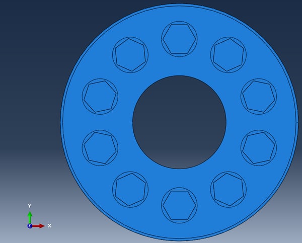
The used flange model can be seen below.
- Flange steel S355
- Material model: Linear elastic
- Yield strength: 295 MPa
- The bolt holes have a diameter of 20 mm.

Assembly Model
- The assembly model is created with no gap between washer and flange.
- The total number of bolts used is 10.
- Make sure that the bolts are instances of one bolt part (e.g. using the create radial pattern button enclosed in red color box below). Also make sure that the naming is consistent (by properly naming the bolt part-see details below). This ensures that the Python script will be successfully executed.

Applying Pretension
Step 1 : Part Module
In the bolt-1-rad-1 part, once the bolt geometry is complete, do the following:
1. Create a datum plane half-way through the bolt shank and a datum axis that represents the axisymmetric axis of the bolt.
2. Create a cell partition based on the datum plane created in step 1.

3. Create a surface (“Surf-1”) on the bolt-1-rad-1 part, halfway through the bolt shank, based on the partition created in step 2.

4. Create a static load step named “Pretension” after the initial step.

5. Python Script explanation
- The counter (“n”) must have one value greater than the total number of bolts used (10 bolts in this example)
- The datum plane id can be found be double clicking on this feature.
- Attention is advised in order to correctly input the model/step/instance/datum entity names and conventions

- The pretension force magnitude (183217.7 N) is chosen based on the effective cross area of the bolt shank in order to inflict a stress of 720 MPa (80% of yield) upon the bolt.
- For automation purposes, the user can record a macro while completing all steps for creating a bolt load for a single bolt instance(e.g. bolt-1-rad-1) and modify this according to the problems needs. Additionally all the steps performed in this example, can also be found in a text format by viewing Abaqus replay file (rpy).
- Alternatively this script can be directly pasted in the command window within Abaqus CAE once all the above steps have been completed. If done properly, the following will be shown within Abaqus CAE.

Analysis
Boundary conditions and loading should be applied according to the problem at hand. Then the job file should be created and run. In this particular example, no external loading is applied (apart of course from the pretensioning of the bolts) and the assembly is fully constrained (encastre) in its lowermost surface.
Results
Contact Pressure
A contact pressure on flange surfaces screenshot can be seen below. The effect of pretensioning the bolts fades away as we move radially towards the interior or exterior of the assembly (green and blue regions).

Loading on Bolts
For the actual loads acting on the bolts as pretension, the value that we should validate against is 720 MPa (80% of Yield chosen as pretension load).

And by modifying the contour limits so as to more easily validate against the value mentioned, we can clearly see below, that the bolt loads are properly applied since the bolt shanks of all bolts are under that target value stress.

Reminder for Applying Additional Loading
As a last reminder, if in your simulation study, additional loading at a subsequent step(“external loading” in this example) is to be applied, always remember to fix the length of the bolts at that subsequent step, otherwise the pretension loads will keep on acting on the bolts (which is incorrect unless the simulation needs impose so). A relevant screenshot of this modification is shown below:

Are you dealing with bolts all the time, and want to let us do the work for you, or want to learn how to create scripts with Abaqus to automate tedious tasks?

 Advanced Simulation


 Engineering

 PLM
PLM
