 Advanced Simulation


Modern engineering design, particularly in fields such as electronics, telecommunications, aerospace, and automotive, demands an advanced approach to the simulation and optimisation of complex systems. In response to the growing need for tools that enable fast, accurate, and automated analyses, the market offers numerous specialized computer-aided engineering (CAE) software solutions. Among these, Isight a tool for simulation process management and optimisation and CST Studio Suite an advanced 3D electromagnetic analysis environment hold a prominent position. The integration of capabilities from both programs through co-simulation opens new perspectives for comprehensive analysis and optimisation of technical systems.
Isight, developed by Dassault Systèmes, is a leading tool for creating automated workflows that connect various simulation and computational tools. Users can build complex optimisation processes that incorporate both numerical analyses and experimental input data. One of Isight's key advantages is its flexibility and ability to integrate with a wide range of external programs both commercial and proprietary user-defined codes. Additionally, Isight offers a variety of optimisation algorithms (e.g., evolutionary methods, gradient-based algorithms, Design of Experiments – DOE, etc.), as well as extensive tools for statistical analysis and design space exploration. This empowers engineers not only to find optimal solutions but also to understand the impact of individual parameters on the performance of the designed system.
Conversely, CST Studio Suite, developed by SIMULIA (Dassault Systèmes), is one of the most advanced tools for electromagnetic (EM) simulation. This software enables the analysis of a broad spectrum of electromagnetic phenomena—from very low frequencies, typical for medical devices, electrical machines, transformers, and power systems, to gigahertz frequencies characteristic of communication technologies, radars, antennas, RF circuits, and microwave systems. CST Studio Suite offers diverse solvers in both time and frequency domains allowing for the selection of the appropriate computational method depending on the problem being analysed. It is also crucially important that CST software allows for the analysis of couplings between different physical domains, such as electromagnetism, thermal mechanics, and structural mechanics, which is essential for analysing the impact of environmental conditions on electronic systems.
By combining these two powerful tools—Isight and CST Studio Suite—it's possible to create an automated environment for the design, simulation, and optimisation of complex electromagnetic systems. Co-simulation, which involves the interaction of two or more computational tools within a single simulation workflow, enables accurate representation of interdependencies between different system components and automatic tuning of design parameters. When integrating CST Studio Suite with Isight, users gain the ability to fully automate the EM simulation process and couple it with optimisation algorithms, significantly increasing design efficiency.
This article presents the concept of co-simulation using Isight and CST Studio Suite, focusing on the practical application of this method in the optimisation of an E-type ferrite choke. Both the advantages of integrating simulation and optimisation environments and the key aspects of implementing a workflow encompassing automated electromagnetic analysis and control of model design parameters are discussed. Particular attention is paid to selecting the number of turns and the length of the air gap to achieve an inductance of 12.5 mH while maintaining the magnetic material's operation within the linear range. The presented methodology can serve as a starting point for further analyses and optimisation of magnetic devices, also in the context of their operation under variable operating conditions and different frequency ranges.
Co-simulation methodology of CST Studio Suite and Isight for ferrite choke optimisation
Within this study, a co-simulation process was conducted between the electromagnetic environment of CST Studio Suite and the simulation and optimisation management tool, Isight. The objective of the analyses was to find such design parameters for a choke made of Fe-Mn ferrite material that its inductance would be 12.5 mH, while simultaneously ensuring operation within the linear range of the magnetization curve (i.e., avoiding material saturation).
1. Electromagnetic model in CST Studio Suite
In the first stage, a 3D geometric model of the choke was prepared in CST Studio Suite. An E-type choke geometry, typical for power electronics applications, was adopted. The choke consisted of two E-type ferrite cores and a working air gap in the central leg. The choke's construction is shown in Fig. 1. The variable parameters in the analysis were:
- Number of winding turns
- Length of the air gap (in the central leg of the E-type core)
The core material was defined as Fe-Mn ferrite, with electromagnetic properties (specifically, the B-H curve – Fig. 2) obtained from the manufacturer's technical documentation. Special attention was paid to the nonlinear material characteristic, enabling the assessment of the saturation level. The analysis was performed using a magnetostatic solver, which allows for the calculation of inductance based on the magnetic field distribution for a given excitation current. In the simulation, it was assumed that the choke would operate at a maximum current value of Ic =1 A.
The simulation result was the total inductance value of the choke, determined based on the stored magnetic energy or the analysis of the induced voltage in the winding.

Fig. 1. 3D view of the choke model developed in CST Studio Suite

Fig. 2. View of the B-H characteristics of the used ferrite material
2. Isight workflow configuration
After preparing the base model in CST, the following workflow was built in Isight (Fig. 3), comprising the following components:
- CST Component – a module for remote control of CST, with the ability to parameterize geometry and automatically run simulations.
- Optimizer – a component responsible for conducting the optimisation (in this case, a genetic algorithm (GA) was used).
- Constraint Evaluator – evaluating physical constraints, such as material saturation.
The input parameters in Isight were:
- Number of turns (integer value in the range: 230–330)
- Length of the working gap on the central leg (in the range: 1–4 mm)

Fig.3. Workflows in the Insight program
The optimisation objective was to obtain a static choke inductance value as close as possible to 12.5 mH with a tolerance of:
∣L – 12.5 mH∣≤0.2 mH, for the smallest air gap value
obtained from the optimisation process.
Additionally, a material nonlinearity criterion was introduced. After each simulation, the maximum magnetic flux density (Bmax ) in the ferrite region was analysed and compared with the saturation value (Bsat ). The permissible limit was considered to be:
Bmax ≤0.35 T
3. Optimisation and validation process
Once the environment was configured, the iterative optimisation process began. Isight controlled the values of the number of turns and gap length, modified the geometric model in CST, ran simulations, collected results, and directed subsequent iterations. The process was fully automated. The spatial distribution of the objective function, along with the points obtained from the optimisation process for the considered parameter values, is presented in Fig. 4, while the spatial distribution of the objective function, including the penalty function, is shown in Fig. 5. As a result of the optimisation process, a working gap value of "air_gap = 1.94 mm" and several turns "N = 246" were obtained. For these defined values of the decision variables, a static inductance value of L=12.52 mH was achieved with a Bsat =0.285 T.

Fig. 4. Spatial distribution of the objective function for the considered example
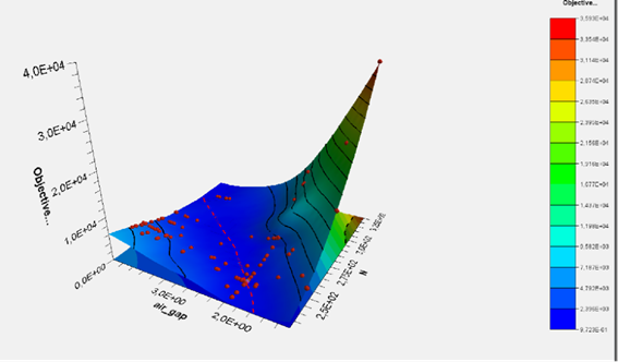
Fig. 5. Spatial distribution of the objective function with respect to the values of the penalty function for the considered example
After obtaining the final solution, additional validation simulations were performed in CST to confirm correct operation under various current conditions. In the simulation, a static inductance value of 12.56 mH was obtained for the choke. It was also verified that there were no local areas where the permissible magnetic flux density was exceeded, which could lead to local core saturation.

Fig. 6. Distribution of the induction vector in the optimized choke circuit
4. Conclusions from the optimisation
The performed co-simulation using CST Studio Suite and Isight confirmed the high effectiveness of the integrated approach to designing and optimizing passive components, such as ferrite chokes. By employing an automated workflow, it was possible to meet strictly defined functional requirements (achieving a static inductance of 12.5 mH) and physical constraints (operating within the linear material characteristic, i.e., without core saturation).
As a result of the optimisation, it was possible to:
- Determine the optimal number of turns and working gap length, ensuring the desired inductance value while maintaining a safety margin with respect to the ferrite material's saturation value.
- Reduce design time by automating the iterative process of selecting geometric parameters without the need for manual simulation execution.
- Verify the magnetic field distribution throughout the core region and identify critical points, which enabled the assessment of local flux density values and confirmation of operation within the permissible material range.
- Confirm that the use of a genetic algorithm effectively identified the values of the sought decision variables.
The results of the optimisation indicate that the integration of simulation and optimisation tools, such as CST and Isight, allows for the efficient, repeatable, and robust execution of complex design tasks. This approach is particularly beneficial when designing inductive components where strong material nonlinearity and strict geometric dependencies affect the functional parameters of the device.

