1. Introduction
PID controllers have been widely used for control design due to their simplicities and non-model based design. However, they lack robustness with respect to uncertainties and external disturbances. This blog post describes a method for developing a mean value model of intake manifold pressure and engine speed for model based idle controller design which can be applied to mean value and crank angle resolved engine models. This post shows the results of a mean value nonlinear model and compares these with the result of crank angle resolved engine model. A linearised model is then derived for controller design. Validation results show the derived nonlinear and linear model can accurately catch the dynamics of Dymola crank angle resolved engine model at the operating point at which linear model is derived.
2. Model development
2.1 Manifold model
Mass flow through throttle can be approximated as
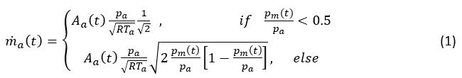
where
Manifold pressure can be modelled as
where
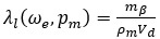
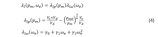
Mass flow into the cylinder can be modelled as
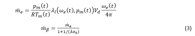
where
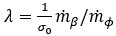
where
2.2 Engine speed model
Engine brake torque can be modelled as
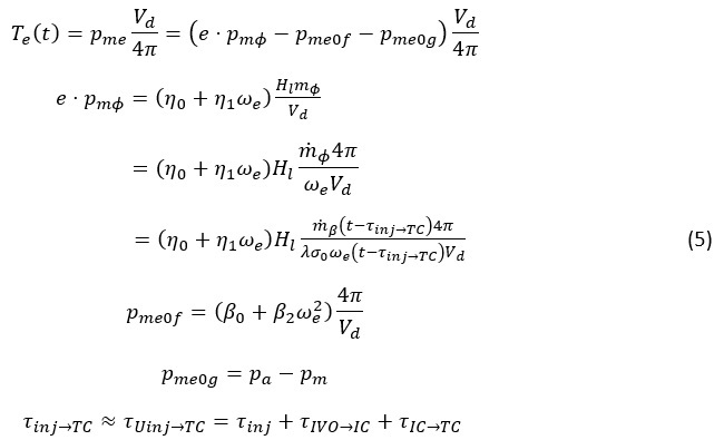
where
Engine speed with a constant inertia
where
2.3 Linearisation of nonlinear manifold and speed model
The combined and simplified manifold pressure and speed dynamics assuming volumetric efficiency and air/fuel ratio are set to 1
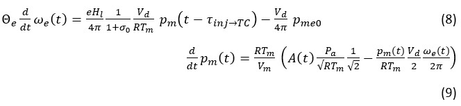
To simplify the notation, the following abbreviations are introduced
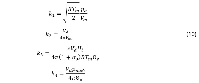
Using these definitions, the combined nonlinear system can be written compactly as
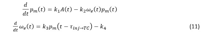
Linearising the equation (11) at equilibrium
yields a second order linear system whose state space description
where
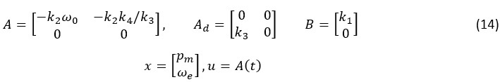
When delay is zero or is neglected then (13) becomes
where
The following section will show validation of the nonlinear model (11) and linearised model (13) in simulation.
3. Model validation
For idle speed control we are interested in the engine speed around 700 to 800 rpm, in this case nonlinear model (11) is linearised around this operating point at 710 rpm. Tuning parameters are chosen as
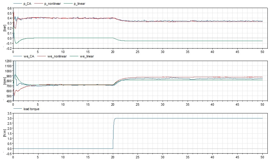
Figure 1: manifold pressure, engine speed and load torque from crank angle resolved Dymola engine model,
nonlinear model (11) and linear model (15) with a constant throttle opening.
Validation result shows dynamics of the engine at its linearised operating point can be accurately represented by its nonlinear and linear model. Model based controller design can then begin to be considered based on nonlinear or linear model. Next blog post will show a robust sliding model controller design and its result for engine idle speed control.
Reference
[1]. L.Guzzella and C.H. Onder, Introduction to modeling and control of internal combustion engine systems, Springer-Verlag Berlin Heidelberg 2004.