A convenient way to pass a number of variables/signals between components or subsystems in Dymola is to use hierarchical connectors.
Modelica supports hierarchical connectors (Connectors which contain sub connectors). As a result, it is possible to connect several sub connectors together with a reduced number of connection lines.
For example, an electrical plug consisting of two electrical pins (sub connectors) can be defined as:
connector Plug
Modelica.Electrical.Analog.Interfaces.PositivePin positive annotation (
Placement(transformation(extent=, rotation=0)));
Modelica.Electrical.Analog.Interfaces.NegativePin negative annotation (
Placement(transformation(extent=, rotation=0)));
annotation (
Diagram(coordinateSystem(preserveAspectRatio=false, extent=), graphics={Ellipse(
extent=,
lineColor={0,0,255},
lineThickness=1)}),
Icon(coordinateSystem(preserveAspectRatio=false, extent=),
graphics={Polygon(
points=,
lineColor={0,0,255},
fillColor={255,255,255},
fillPattern=FillPattern.Solid)}),
Documentation(info="<html>
</html>"));
end Plug;
With one connect (..) equation, either two plugs can be connected (and therefore implicitly also the positive and negative pins) or a Pin connector can be directly connected to the positive or negative pin of a Plug connector, such as connect (resistor.p, plug.positive). See figure below:
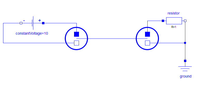
Figure: Two plugs connected using a single connection line. Each plug has an electrical circuit connected to it via its pins.
Any type of signal or connector can be used in a hierarchical connector: Real input and physical connectors, etc. and there is no limit to the number of sub connectors.
However, contrarily to a Bus, a hierarchical connector is not an expandable connector. This means that we cannot connect it to a connector type that has not previously been declared in the hierarchical connector itself.
Hierarchical connectors are then a good way to reduce the number of connections in the diagram layer of a model by grouping signals together, thus making the model tidier.