 MBSE
MBSE
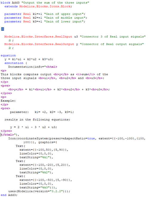
This blog post will be outlining the structure and syntax of a class created within Dymola; the differences between the classes and what must be included for the structure to be correct. A future post will go into more detail about the different elements within a class and the implementation of calculations.
. 
Text Layer
The text layer is where most of the Modelica coding takes place; but this can also be relevant when modifying components in the diagram layer. Descriptions and differences between the layers are described in Dymola Basics 2: Layers of a Model within Dymola. To leave the text layer of a model the syntax must be correct; classes don't need to check without errors, but the use of the language must.
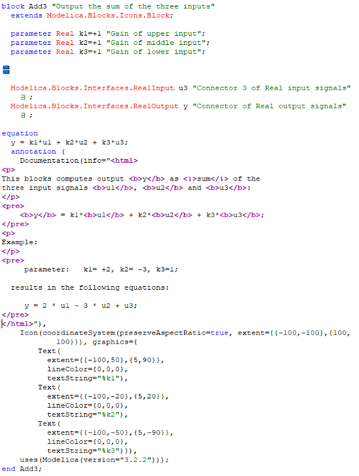
The first thing to note is that there can be lots of different types of elements in a class, and each needs to be treated slightly differently. On the right is a simple example, Modelica.Blocks.Math.Add3 (slightly modified for demonstration purposes). While the order shown here is typical, some of it can be different; but when making your own classes this order does follow the logical route when creating a class is recommended.
Class Restriction
The first thing in any class must be the Class Restriction, which defines what and how class will be used. This restriction is important as each class can have different restrictions and uses. The next section briefly describes the different classes.
Next is the Name of the class. This can only contain letters, numbers and the underscore symbol and the first character cannot be a number. Finally the class should, but is not required to, have a Description which is contained in double quotation marks which can contain all other characters.
Example: classRestriction NameOfClass "Description of class"
An example of the first line is:
model Universal
"Universal joint (2 degrees-of-freedom, 4 potential states)"
The final line of a class must be an end statement. This starts with end and then the Name of the class followed by a semicolon:
end NameOfClass;
an example of this is: end Universal;
Class Restriction Uses and Contents
Each Class Restriction has certain restrictions to what the class can contain, aiding their application. Here is a list of the common classes in Modelica with their associated structure and use:
model - general class
Can contain acausal (bi-directional) connectors and other components and contain an equation section.
block - for block diagrams
Public elements must only be inputs, outputs or parameters. Used where the causality is known and the direction is maintained. Protected elements can be acausal and contain an equation section.
function - mathematical functions
Similar to block class with inputs, outputs and parameters. Contains Algorithm section, instead of an equations, which is procedural code.
In Algorithm sections variables must be on the left, expressions on the right.
record - define a data structure
Can only contain parameters, variables and constants. No equations or Algorithms.
connector - declare the structure of ports or interface points
Only contains variable declarations, no equations. There are 3 types of variables:
- non-flow (across) - quantities that are equal across a connection
- flow - quantities that sum to zero across a connection
- stream - ensure that bi-directional flow of enthalpy is reliable
package - define libraries of classes, Can only contain declarations of classes, used to organise libraries.
type - extension to the built-in types
Can only contain definitions of types with associated details, e.g. unit and display units.
Class Annotation
As you can see when looking at the image at the top of this post, and almost all published models, there is an annotation before the end statement. An annotation contains additional code to aid the model, such as the description and icon animation definitions; it can also contain simulation preferences and library requirements. Many times, when viewing the text layer, the annotations will be collapsed, hiding all of the annotations and replacing it with a single lower case green a and semicolon: a;
This can be expanded to view what the annotation contains by clicking on the a or right clicking, looking at the "Expand" drop down menu to expand annotations throughout the model.
Tips To Aid Writing In The Text Layer
The easiest way of seeing examples of the use of the Modelica Language is to look at the text layers of published libraries. Published libraries are syntactically correct and most are not protected, allowing viewing of text layers.
Code completion
When writing in the text layer using Ctrl + Space brings up a context menu containing all the words beginning with the letters written so far. This can also be used to aid writing out library paths as it will provide a list of packages/classes when writing a path.
Troubleshooting
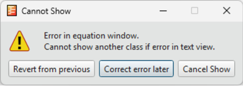
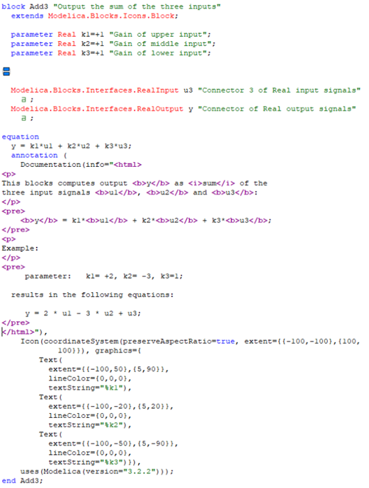
If you attempt to move away from a model but are unable and greeted with an error message that looks like the image on the below, then it is most likely that you have a syntax error. If you go to the Dymola Messages box then it will give you more information as to where the problem is occurring. In the example below it is due to a missing semicolon on a parameter declaration on line 6; this is showing an error on line 8 as it doesn't know that this is a start of a new definition, therefore it thinks that syntax in incorrect.
Modelica (line 8, column 3: Add3)
Expected one of:
";"
","
")"
"constrainedby"
"annotation"
60 (line 9, column 56: Add3)
Expected one of:
identifier
ERRORS have been issued.
When the Dymola Messages box highlights a line then this can really help identify the problem area. But be aware that if there is a syntax error within brackets then it will signal that the error is found in the first line of the definition. This means that you need to check the modification of the class.
To help you get around the text layer, the line that a cursor is on is displayed in the bottom right corner of the screen. You can also navigate to any line by hitting Ctrl + G and selecting the line you want to go to.
Generic Definitions Of Elements Within Classes
This blog post goes into a little more detail regarding variable definition and syntax in equations and algorithms. The Class Restriction of a class can restrict the ability to use certain elements and methods, also described in the previous post.
Variable
Variables can take many forms, mainly dependent on the type defined. They can be singular or a matrix of Reals, Integers, Booleans or Strings, or can be more complex containing a set of information. The same format can form as a base and can be expanded with prefixes to define the different uses, with the same syntax. If the variable is left without a prefix then it will not appear in a parameter dialog box, and it should only used within the class. If a variable has been defined then it must be calculated somewhere in the class or it will cause an error.
Variable definitions are formed from a type definition, a name and can include a description in quotation marks and finished with a semicolon.
Type nameOfVariable "Description of variable";
An example of this could be:
Modelica.SIUnits.Velocity v "Velocity of flange";
Type definitions are very useful when defining a variable as they can contain information that can help build a model. You can define any variable using the basic Real, Integer, Boolean or String types, and for all other than Real this is common. But when defining a Real variable there can be units, display units, type grouping associated with the variable. These are all implemented when you define a type referencing a type class, all common types are contained in Modelica.SIUnits. This allows Dymola to check unit matching, switch between units when plotting and when defining parameters.
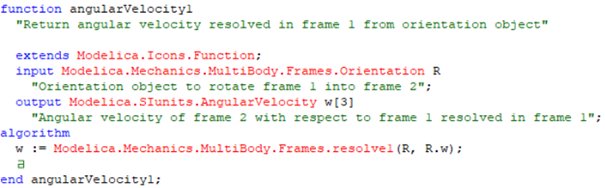
There are some points where a variable type is a record, such as in Modelica.Mechanics.MultiBody. Frames.angularVelocity1, shown on the right, R references the Modelica.Mechanics.MultiBody. Frames.Orientation record. This allows the variable to contain a set of 2 Real variables, T and w, both of which are needed to define the output. This saves requiring to define both when they are associated.
Variable Sizes
Variables do not need to be singular in their definition, they can be vectors or matrices. Such as in the case of a multibody velocity, which is defined in terms of x, y and z velocity. This can be applied by using the square brackets to define the size either after the type definition or the name of the variable. demonstrated in the image, w is a multibody angular velocity. When populating vectors the format is to use curly brackets with commas between each element.
parameter Modelica.SIUnits.Velocity[3] v = {1,0,0}
"Velocity of frame";
or
parameter Modelica.SIUnits.Velocity v[3] = {1,0,0}
"Velocity of frame";
When defining the size of a matrix the size of each dimension is separated by a comma, whereas when populating the matrix the rows are separated using a semicolon:
parameter Real T_rel[3,3]=[1, 0, 0; 0, 1, 0; 0, 0, 1] "Relative transformation matrix";
There are some instances where the size of the array is not know when creating a component, in those instances a colon is used in place of the size.
parameter Real data[:,:] "Matrix of data";
Variable Prefixes
Below are a few of the most common variable prefixes:
parameter
Parameter definitions are similar to the variable definition, but include the parameter definition at before the type. They are variables that are fixed after initialisation, therefore cannot be calculated using time changing variables. Parameters appear in the parameter dialog box for a class.
While any variable can contain an annotation, they are very useful when defining parameters as they can control the appearance of them in the dialog box. As with any annotation, most of the time they will appear as a green "a" as they are collapsed, and can be opened by clicking on them. They are not required when defining a parameter, and if a user inputs just the letter "a" then this causes an error.
parameter Modelica.SIUnits.Mass m=1 "Mass of the body" a;
input
Commonly used in functions, they are dynamic inputs variables that are used as an input to the calculations. They appear in the class's dialog box can be used to reference other dynamic variables when used.
output
Similar to the input, they are used to interface with other classes when a function is used.
final
A final prefix is used to restrict modification when using the class. For example, when a constant is not intended to be changed but is used throughout a model then a final parameter can be used, which doesn't appear in dialog boxes but is fixed at initialisation.
final parameter Modelica.SIunits.Acceleration g=9.81 "Gravitational acceleration constant";
The final declaration can also be used elsewhere when a parameter is propagated and the link is not intended to be broken; or when the choice of a replaceable component has been made and shouldn't be changed for anything else.
Component definitions
When a class is used within another it is a component. Majority of the time it is preferable to modify components in the diagram layer where possible; this maintains a correct syntax and you don't need to worry about getting the language wrong. But sometimes it may become necessary to modify them in the text layer. For this the layout is very similar to using variables, with a couple of key differences.
Component definitions are formed from a class path, a name and can include a description in quotation marks and can include annotations and finished with a semicolon:
Modelica.Mechanics.Rotational.Components.Damper damper(d=0.1, useHeatPort=true) "1D rotational damper" a;
The key difference that is found when modifying a component is that it is done within brackets after the name, where parameters/inputs/components are modified by name. Each parameter change must be separated using a comma.
Modifications of components can rely on calculations, as long as the variability and syntax matches. For example you are unable to use a time varying variable to modify a parameter; likewise you are unable to define an Integer parameter using a Real parameter.
In many cases it is useful to propagate the parameters to a higher level to constrain the behaviour of the class to a single group of parameters.
Annotations normally contain placement information which controls the location in the diagram layer.
replaceable definition
Components and functions can be replaceable to allow extended variability of a class. This is utilised most easily by right clicking on the replaceable component and selecting Change Class. There is an extended blog post describing this detailing Inheritance within Dymola. It is a more advanced type of class control and can make it considerably more complex.
Protected and public variables
Within classes it can be useful to restrict all the internal variables (only used internally, not of use outside the class) to internal use only. Dymola has the ability to limit the view and access to variables if they are declared in a protected section.
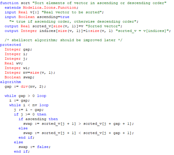
When looking at Modelica.Math.Vectors.sort (shown on the right) there are a lot of variables such as gap or wv that are not of use externally. The inputs and outputs have been defined and these are the variables that are available to be modified and used outside the model. Below those variables is a protected definition and then internal variables following it.
All elements within a class are public unless made protected. Multiple sections of public and protected elements can exist. For a element to be public either no protected definition is made before the declaration of the element; or a public definition is made after a protected definition.
input Modelica.SIUnits.Velocity v[3] = {1,0,0}
"Velocity of frame";
protected
Integer yIndex = 2
"Index of the y velocity of a multibody velocity vector";
public
output Modelica.SIUnits.Velocity v_y = v[2]
"y velocity of frame";
Above shows an example of 2 sections of public code, the input and output, and a protected variable, yIndex. But it is not recommended to have multiple public or protected sections as it can make the text layer confusing and difficult to navigate. For more information on keeping your code layer organised, there is a blog post on the Claytex website about how to clean up a Dirty Code Layer.
Calculations
This blog post focuses on the syntax used in equations and algorithms and the difference between the two.
Equation Sections
Models and blocks primarily use an equation section to define the calculations of the class. This section is started with a definition "equation" following which variables can be constrained. A calculation can be either side of the equals sign, as equations are used to constrain equality. Connections are also defined in this section. Every line of an equation must be ended with a semicolon.
equation
y = k1*u1 + k2*u2;
u1/u2 = z;
The order in which they are defined does not matter, as Dymola's Symbolic Manipulation will rearrange the equations at compilation. As long as all variables have been constrained but not over constrained.
Algorithm Sections
Algorithms are procedural versions of equations, meaning the order is maintained when simulating. In Algorithm sections the variables must be on the left of the equality sign, with the calculation on the right. Instead of a single equals sign a colon followed by an equals sign is used.
algorithm
y := k1*u1 + k2*u2;
z := u1/u2;
Initial Equation/Algorithm sections
Classes can have initial equation/algorithm sections. These sections follow the same rules as before but are run during initialisation.
Mathematical and Equality Operators
Real
These are the operators that are primarily used on Real or Integer variables
|
a+b |
- |
Addition |
|
a-b |
- |
Subtraction |
|
a*b |
- |
Multiplication |
|
a/b |
- |
Division |
|
a^b |
- |
Raise to the power, i.e. 2^2=4 |
Boolean
These qualities produce a Boolean result
|
a==b |
Compare variables for equality. Cannot be used to compare Real variables. |
|
a-b |
Compare a to see if it is less than b. |
|
a=b |
Compare a to see if it is less than or equal to b. Cannot be used to compare Real variables. |
|
a>b |
Compare a to see if it is greater than b. |
|
a>=b |
Compare a to see if it is greater than or equal to b. Cannot be used to compare Real variables. |
|
a<>b |
Compare variables for inequality. Cannot be used to compare Real variables. |
|
A and B |
true if both A and B = true. A and B must be Boolean expressions. |
|
A or B |
true if either A and B = true. A and B must be Boolean expressions. |
|
not A |
true if A = false. A must be Boolean expression. |
Functions
Equations and algorithms can use functions to define relationships. They need to reference the path of the function, and the inputs put into a bracket, modifying the function. The inputs can reference specific inputs to modify, otherwise the input order must match the order they given. If a function has multiple outputs then they need to be within a brackets in the correct order.
v := Modelica.Math.Vectors.length({v_x, v_y ,v_z});
(sortedVector, sizeOfVector) = Modelica.Math.Vectors.sort({1, 2, 3, 4, 5, 6, 7, 8, 9}, true);
There are some common functions that do not require an path, they are contained in the Modelica Reference and Dymola Commands libraries:
v = der(x);
y = sqrt(x);
Conditional Statements
Conditional statements are available in Modelica to be able to control the effects of equations and algorithms. They take the form of if, for, when and while statements that can be used to change behaviour of variables by changing the calculation. The condition needs to be in the form of a Boolean, either a variable or a calculation. In all cases the statement must be ended with an end declaration.
If Statements
If statements define equations by operating conditions. They can define any number of equations but each condition must define the same number of relationships. There has to be an else statement used unless determining a constant or parameter. Different equations sets are separated either by else or elseif sections. The statement must be ended with an end if; declaration.
if condition then
expression
elseif condition then
expression
else
expression
end if;
for example:
if angle > 0 then
y = 1;
elseif angle < 0 then
y = -1;
else
y = 0;
end if;
If statements can also be used in equations:
variable = if condition then expression elseif condition then expression else expression;
y = if angle > 0 then 1 elseif angle < 0 then -1 else 0;
When Statements
When statements are used to define a set of equations that are valid at a particular event instant.
when condition then
expression
elsewhen condition then
expression
end when;
for example:
when time > 1 then
y = time;
elsewhen time > 2 then
y = 3;
end when;
In this example y = 0 until time = 1, then from that point y = 1 until time = 2 then from that point onward y = 3.